Meshlet size tradeoffs
16 Jan 2023When working with mesh shaders to draw meshes, you need to split your source geometry into individual units called meshlets. Each meshlet would be processed by one mesh shader workgroup, and when compiling this mesh shader you need to specify the maximum number of triangles and vertices that the meshlet contains.
These numbers are subject to some hardware limits. On current drivers, AMD, Intel and NVidia expose limits of 256 triangles and 256 vertices through EXT_mesh_shader Vulkan extension, but NVidia advertises a higher limit of 512 triangles & 256 vertices through NV_mesh_shader. These limits are the ones you’d want to use when building your meshlets, eg when using meshoptimizer’s meshopt_buildMeshlet function - but what numbers do you actually use?
Note: this was originally posted as two cohost posts, Meshlet sizing theory and Meshlet sizing efficiency. 🐞
There are hardware efficiency implications here that we will explore in a future post but let’s first try to get a sense for the abstract tradeoffs.
Vertex transform
Let’s first explore the relationship between number of vertices and number of triangles. For that, let’s assume that our source mesh is two-manifold, and as such our meshlet is a subset of a larger two-manifold mesh. To make things easier, let’s assume that each meshlet can be “flattened” - which is to say, we can lay out the meshlet triangles on a plane without triangles overlapping1.
This allows us to view a meshlet as a planar graph and to apply Euler’s formula: V-E+T=12. V and T are numbers of vertices and triangles, respectively, and E is the number of edges. Every triangle has three edges, and in every meshlet that was created out of a two-manifold mesh we have unconnected edges that lie on the border of a meshlet and connected edges.
Let’s say that our meshlet has P unconnected (perimeter) edges; then 3T=2E-P (as 3T would count every non-perimeter edge twice), so E=(3T+P)/2. Plugging this back into Euler’s formula and simplifying we get 2V=2+T+P. You can validate this on simple examples; a single triangle has V=3 T=1 P=3; a quad has V=4 T=2 P=4.
The mesh shader execution model implies that each vertex within the meshlet will be unpacked/transformed once, but if the vertex is shared between two meshlets then it will be transformed redundantly. As such, the number of vertices shared with other meshlets - which is the same as the number of perimeter edges, P - needs to be minimized.
For very large meshlets, optimal P tends to get insignificantly small as V and T grow large. Intuitively, P grows as a square root of V - for example, an N^2 quad grid has (N+1)^2 vertices, 2*N^2 triangles, but only 4*N perimeter edges. So for very large meshlets, 2V approaches T (there are approximately half as many vertices as triangles); however, our limits tend to be reasonably small, and as such a 1:2 vertex:triangle ratio is unreasonable to expect.
We can look at the ratio between P and T as, approximately, transform waste - if each perimeter vertex is only shared between two meshlets, then for a large source mesh that is split into K meshlets, we’ll get K*T triangles and K*P redundant vertex transforms, so we get P/T redundant vertex transformations for every triangle - ideally we’d like that to be as close to zero as possible. We can also compute ACMR, which is a metric traditionally used for vertex transform optimization, by dividing V by T, for which 0.5 is the optimal (but unreachable) target.
To make this a little more concrete, let’s look at how grid-like meshlets look like at different sizes. For simplicity, let’s look at the maximum vertex count of 32, 64, 96, 128 and 256, and let’s use a simple script to find the best grid-like configuration:
v limit 32 : best 4 x 5 v 30 t 40 p 18 ; p/t 0.45 acmr 0.75
v limit 64 : best 7 x 7 v 64 t 98 p 28 ; p/t 0.29 acmr 0.65
v limit 96 : best 7 x 11 v 96 t 154 p 36 ; p/t 0.23 acmr 0.62
v limit 128 : best 10 x 10 v 121 t 200 p 40 ; p/t 0.20 acmr 0.60
v limit 256 : best 15 x 15 v 256 t 450 p 60 ; p/t 0.13 acmr 0.57
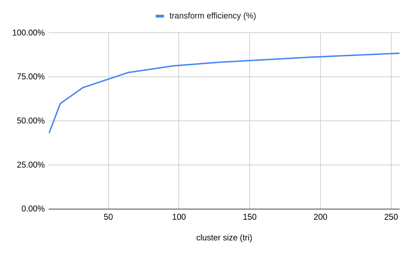
This information alone should lead us to an obvious conclusion - large meshlets are good, because they maximize the effective vertex reuse and thus minimize the vertex transform cost. For EXT_mesh_shader limits we’d outlined earlier3, we need to limit the triangle count to 256, which ends up with the actual limits of around 144 vertices / 242 triangles for regular grid patches (ACMR 0.60); for NV_mesh_shader, we can max out the 256 vertex limit for a slightly better 0.57. In practice there’s no reason to use regular grid patches, but it’s important to note that experimentally we see that the optimal grid configuration for a given limit looks like a square more than a long strip, since it minimizes the perimeter length.
Alas, things are not quite as simple as “bigger meshlets = better” because there are other contributing factors in this problem.
Meshlet culling
First let’s look at how meshlets of different sizes behave wrt meshlet culling. In a mesh shading driven pipeline you’d expect some amount of per-meshlet culling to happen - after all, if that isn’t happening at all, why use mesh shaders to begin with? niagara, an experimental toy renderer written on YouTube streams, implements - as of today! - frustum culling, occlusion culling and backface culling for meshlets. For each culling mechanism we can compute efficiency - how many triangles can we remove from the rasterizer by implementing a given culling scheme, in this case when working on meshlet granularity?
A meshlet with a higher triangle limit is, naturally, larger. While this has some impact on frustum culling, it has a more noticeable impact on occlusion culling4 efficiency. Any numbers here are going to be highly scene-dependent and the scene it is taken on is very artificial (but full of kittens!) so take this with a grain of salt, but on the graph below you can see that on our test scene occlusion culling efficiency drops from ~80% for a meshlet with size 64 to ~66% for a meshlet with size 256 (triangles). This is a significant decrease and can easily offset any gains in transform efficiency in practice.
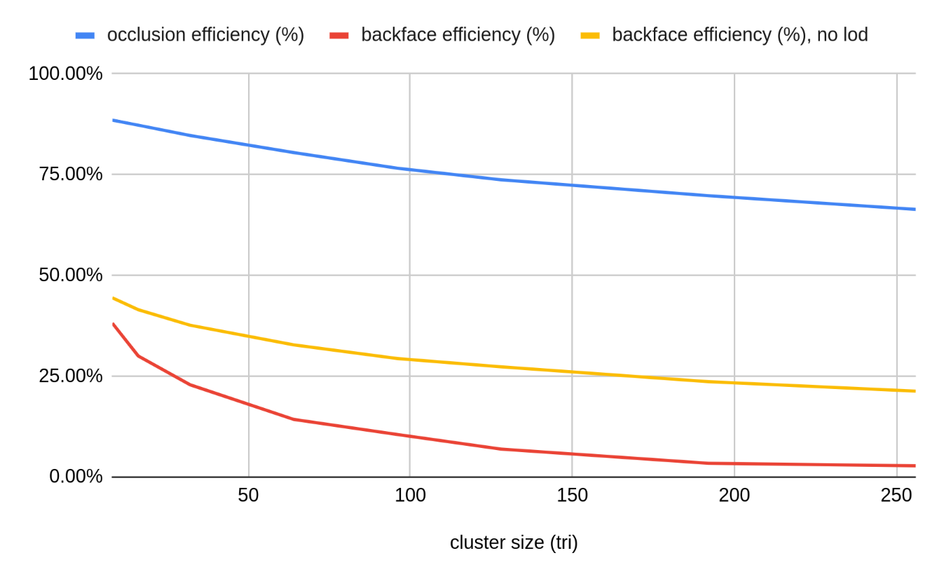
The picture is similarly bleak for backface culling. To perform backface culling on meshlets without considering individual triangles5, we need to perform cone culling based on the aggregate normal cone generated by meshoptimizer. This test works well when the normal cone is tight - that is, when all triangles in a meshlet have similar orientation. However, the more triangles are in a meshlet, the higher is the chance that they will have normals that point in different directions. While it is possible to gather triangles into meshlets using normal clustering alone, that results in a lot of unconnected triangles which results in significant issues with transform waste, so this is pretty unavoidable.
Indeed, normally we’d expect that 50% of triangles on average are backfacing, but the efficiency of meshlet level backface culling drops to 14% with 64-triangle meshlets and all the way to 3% for 256-triangle meshlets - making the culling test barely worthwhile for very large meshlets! In part this is a problem because we use level of detail, and as such a lot of geometry that we render is far away and relatively coarse. Indeed, disabling level of detail gets us somewhat more respectable 32% for 64-triangle meshlets and 21% for 256-triangle meshlets - unfortunately this isn’t very realistic since at that point we’re pushing close to 1 billion triangles in our test scene.
Hardware occupancy
It’s also important to note that larger meshlets lead to a higher mesh shader threadgroup memory footprint. The mesh shader computation model implies that a given mesh shader outputs V vertices and T triangles from the threadgroup, and the memory for this needs to be allocated out of a finite storage. The details vary per GPU vendor and we’ll discuss some of them in a future post; however, the number of vertices can pretty significantly affect this memory footprint as a single vertex likely needs at least 32 bytes of output memory and likely more if more than a couple varying outputs are written. The issue with using too much memory here is the possibility of reduced occupancy - since the threadgroup memory is allocated out of a hardware-specific fixed amount of memory, large footprint leads to only being able to run a few different threadgroups on an individual compute unit concurrently. This can be an issue because it reduces execution efficiency - having multiple different workgroups that execute “at the same time” helps GPUs hide memory and ALU latency. Unfortunately, vendors currently don’t publish guidance on specific numbers here for mesh shading, and the details may vary significantly on different vendors.
Additionally really small meshlets, e.g. with 8 or 16 triangles, are going to suffer from threadgroup execution efficiency as well, due to mesh shader computation model - as typically one meshlet would be processed by one threadgroup, and AMD and NVidia GPUs need at least 32 threads in a threadgroup.
Overall, all of this says that we need to somehow balance “larger is better” from the transform perspective with “smaller is better” from culling and execution efficiency perspective.
Conclusion?
Looking at the original NVidia mesh shader publication, one concrete number they recommend is 64 vertices and 84 or 126 triangles per meshlet. 126 feels like a typo but it’s not - NVidia implementation allocates output memory for primitive indices in groups of 128 bytes and has to leave a little extra room to store primitive count, so 84*3=252 bytes and 126*3=378 bytes are good targets for that hardware. From our previous post we know that with 64 vertex limit we can at best expect 98 triangle patches for a regular grid; thus while 84 isn’t going to run at quite the peak efficiency, it is likely reasonable as a “default” guidance to use V=64 T=84, as a compromise between higher culling efficiency of smaller meshlets, and transform waste (V=64 T=126 is also a good target although it will typically waste a little bit of primitive memory as we’d realistically go up to <100 triangles per meshlet).
Unfortunately, applying this configuration on AMD hardware will lead to suboptimal execution due to the specifics of how AMD hardware supports mesh shaders - and it’s also not clear whether “transform waste” is important there relative to some other factors! This is a subject we’ll explore in a future post, as it requires looking closely at how exactly mesh shaders execute on different hardware.
-
This is not necessarily the case in general as not all subsets of two-manifold meshes can be planarized, but it’s a reasonable generalization. ↩
-
Euler’s formula says
V-E+F=2but it treats the infinitely large region outside of any face as one, soF=T+1. ↩ -
256/256 is currently the de-facto common denominator across all vendors that have an implementation of
EXT_mesh_shader, as well as the minimum set of limits required by the spec - however, there are other important limits to keep in mind that we will discuss later. ↩ -
Intuitively, frustum culling of individual meshlets is mostly important around the screen boundary, whereas occlusion culling of individual meshlets is important everywhere. ↩
-
The renderer implements per-triangle culling as well but the efficiency numbers above are gathered with all triangle-level culling disabled. ↩
| « Approximate projected bounds | Fine-grained backface culling » |