Fine-grained backface culling
28 Apr 2023Backface culling is something we take for granted when rendering triangle meshes on the GPU. In general, an average mesh is expected to have about 50% of its triangles facing away from the camera. Unless you forget to set appropriate render states in your favorite graphics API, the hardware will reject these triangles as early in the rasterization pipeline as possible. Thus, it would seem that backface culling is a solved problem. In this post, however, we’ll explore a few alternative strategies that may or may not improve rendering performance.
Standard backface culling
As long as you’re setting up backface culling in your graphics API, for example by using VK_CULL_MODE_BACK_BIT in Vulkan, the hardware will perform backface culling automatically. Any backfacing triangle will be culled early in the triangle setup process, typically by a fixed function unit. Triangle setup typically can process a small number of triangles per cycle per geometry engine, and the triangle rejection rate may be a small multiple of that - the performance will certainly vary by the GPU vendor and by the GPU model. For example, according to the RDNA whitepaper, Navi GPUs cull two primitives per clock per “primitive unit”, of which Radeon 5700 XT has four - adding up to rejection rate of 8 triangles per clock. The 2-to-1 ratio of cull throughput to processing throughput is typical as half of the triangles will be culled on average.
On some GPU drivers, the culling may be implemented in “software” and run in a shader stage; we will cover this later in this post.
Cluster cone culling
In more recent GPU architectures, the geometry pipeline gained more flexibility with the introduction of task and mesh shaders. NVidia GeForce GPUs support task/mesh shaders starting from 20xx series (Turing), and AMD Radeon GPUs support them starting from 6xxx series (RDNA2), although there’s some amount of impedance mismatch for AMD between the exposed programming model and the hardware support, that has been improved in 7xxx (RDNA3). Task/mesh shaders can be used in Vulkan (via VK_EXT_mesh_shader) and in DirectX 12 (via shader model 6.5).
With these extensions, coarse grained culling of geometry becomes feasible: the geometry is split into a number of “meshlets”, each of which is a small number of triangles, and the task shader can reject meshlets if no triangles in the meshlet are visible. As long as this check can be done efficiently (and conservatively), this could improve rasterization performance on geometry-dense scenes, as the culling is performed in batches of triangles.
For the purpose of this article, backface culling can be done on meshlet granularity by using cluster cone culling. For each meshlet, the intersection between all negative half-spaces of all triangles in the meshlet is approximated with a cone, such that any point in that cone is simultaneously in all negative half-spaces - if the camera is in this cone, all triangles are backfacing and do not need to be rendered. meshoptimizer provides algorithms for splitting meshes into meshlets and computing bounding information, and you can look at a full end-to-end integration of this technique in niagara renderer.
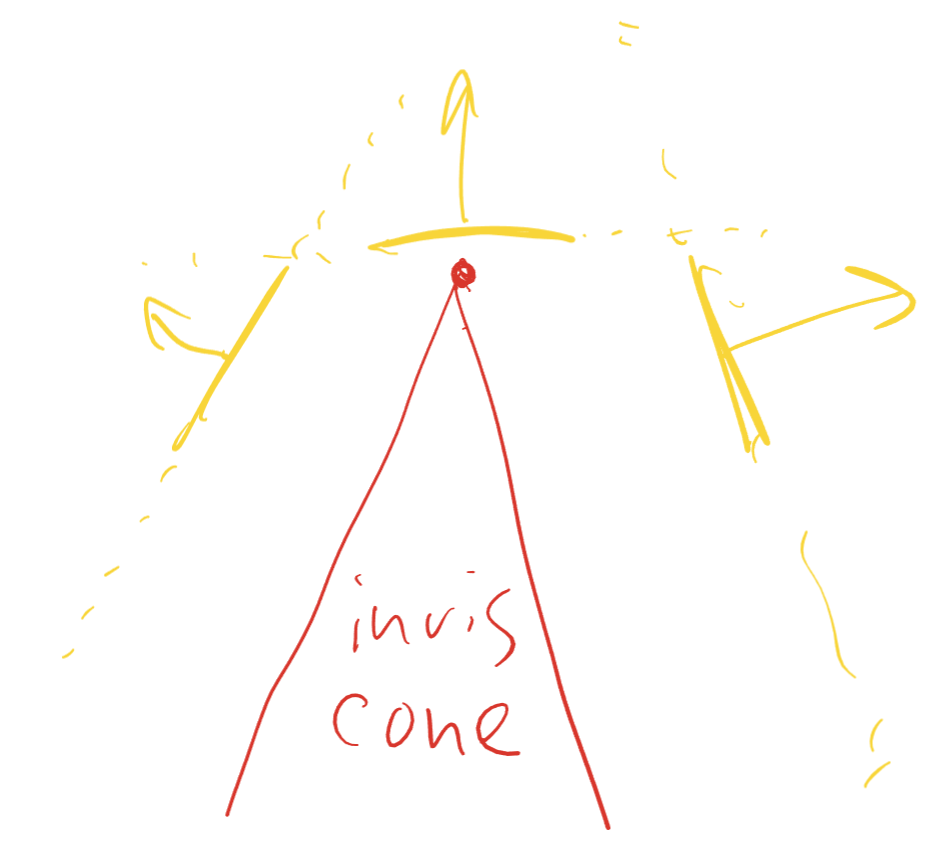
This test is cheap and coarse, which makes it a good candidate for task/mesh shaders. However, it’s also very conservative: while on average we’d expect 50% of triangles to be backfacing when using 124-triangle clusters and a single cone per cluster, cone culling can typically reject only up to ~25% on dense and reasonably smooth meshes, and the rejection rate will be lower on meshes with larger triangles or more complex topology (for example, on Lumberyard Bistro interior scene the rejection rate is just 4%)1.
While the cone is an imperfect approximation, fundamentally on meshes with large triangles or sharp changes in local curvature coarse backface culling is bound to be much less effective, as triangles with different orientations will be mixed together in the same meshlet. This can be mitigated by grouping triangles into meshlets by orientation, but that introduces a lot of topological seams that hurt transformation and rasterization efficiency, and results in a poor tradeoff2.
Bruteforce backface culling
With mesh shader execution model, every meshlet vertex gets transformed to clip space as a result of mesh shader threadgroup invocation. Between this, and the presence of meshlet-local topology, it’s trivial to perform backface culling in the mesh shader manually. In Vulkan, this can be done by outputting gl_CullPrimitiveEXT for each primitive3.
To perform backface culling, we need to save the vertex position in clip space into threadgroup storage:
vertexClip[i] = vec3(clip.xy / clip.w, clip.w);
and compute the result of backface culling for each triangle:
gl_MeshPrimitivesEXT[i].gl_CullPrimitiveEXT =
    vertexClip[a].z > 0 && vertexClip[b].z > 0 && vertexClip[c].z > 0 &&
    (vertexClip[b].x - vertexClip[a].x) * (vertexClip[c].y - vertexClip[a].y) >
    (vertexClip[c].x - vertexClip[a].x) * (vertexClip[b].y - vertexClip[a].y);
Note that while backface culling simply requires computing the sign of the triangle area in screen space, because this computation is done after post-perspective divide, we can only use the result of the test when all vertices are in front of the clip plane. This can be efficient if we need to perform other forms of culling, such as small primitive culling, but if we only need to do backface culling then we can use a more efficient formulation suggested in Triangle Scan Conversion using 2D Homogeneous Coordinates:
// for each vertex
vertexClip[i] = clip.xyw;

// for each triangle
gl_MeshPrimitivesEXT[i].gl_CullPrimitiveEXT =
    determinant(mat3(vertexClip[a], vertexClip[b], vertexClip[c])) > 0;
Either of the above formulas results in rejecting backfacing triangles precisely, reaching ~50% culling efficiency. But, why repeat the work the hardware is doing anyway - wouldn’t a fixed function unit be more efficient?
As briefly noted before, on some hardware when using traditional rasterization pipeline, the driver may end up doing some amount of per-triangle culling in the synthesized shaders. Notably, on AMD GPUs radv driver - and likely other drivers - does this for backface, frustum, and small primitive culling, using some heuristics to decide whether this is worthwhile.
The intuition behind why this can be beneficial lies in the imbalance between fixed function geometry units and shader units. Going back to Radeon 5700 XT as an example, with its four primitive units it can cull 8 triangles per cycle. At the same time, that GPU has 40 compute units, with each unit dispatching up to 64 scalar multiply-adds per cycle, which adds up to ~2560 multiply-adds per cycle. A 3x3 matrix determinant (above) takes ~9 scalar multiply-adds, so theoretically we should be able to cull ~280 triangles per cycle using ALUs. Of course, this speed of light computation omits a lot of details, and some of the shader units may be busy executing other workloads (although for geometry-heavy passes like depth prepass or shadowmap pass the bottleneck is likely going to be in rasterization), but ultimately it’s clear that in certain cases it’s possible to dramatically outperform the fixed function culling hardware.
In fact, because AMD drivers tend to use shader culling when using traditional rasterization pipeline (at least, on desktop), using some form of fine-grained shader culling may be required to reach performance parity with mesh shading pipeline, as - at least as of this writing and on radv - mesh shaders do not get any form of shader culling by default.
Precomputed triangle visibility masks
While 9 multiply-adds per triangle is not that much, it can be tempting to omit these computations altogether and find a more compute efficient way to cull triangles. In 2015, the GPU-Driven Rendering Pipelines SIGGRAPH talk introduced a technique for precomputing triangle visibility masks. The space around the center of each cluster is classified into a small number of regions (6 in the talk), and for each region we pre-compute a mask where each bit of a mask corresponds to triangle visibility in that region. The mask has to be conservative - we must record 1 in the mask if the triangle is visible from any point in that region.
Then, at runtime, we classify the camera position into one of the regions and use the corresponding mask to cull triangles using simple bit tests. Other than classification, which can be done in the task shader as the results are shared between all triangles in the cluster, this only requires to fetch the mask - which can be done using scalar loads for each 32-triangle group - and a bit test:
gl_MeshPrimitivesEXT[i].gl_CullPrimitiveEXT =
    maskSide >= 0 && (meshletData[maskOffset + (i >> 5)] & (1 << (i & 31))) == 0;
To compute the region, we need to assign a region index based on the camera position in cluster space. This requires transforming the camera position with inverse object transforms, and classifying the resulting vector using code like this for 6 regions:
int maskSide =
    max(abs(dir.x), max(abs(dir.y), abs(dir.z))) <= meshlets[mi].radius
        ? -1
        : abs(dir.x) > abs(dir.y) && abs(dir.x) > abs(dir.z)
            ? (dir.x >= 0 ? 0 : 3)
            : abs(dir.y) > abs(dir.z)
                ? (dir.y >= 0 ? 1 : 4)
                : (dir.z >= 0 ? 2 : 5);
This is not particularly cheap in abstract but, when done in task shader, the work is shared between all triangles in a cluster and as such has a fairly negligible cost.
Computing the masks is fairly simple: we need to test each triangle against each region of space and see if the region is entirely within the negative half-space of the triangle plane (in which case no point in the region can see the front side of the triangle), or not. This task is made slightly harder by the fact that the region is infinite, but it has a simple algebraic formulation. For example, for a 6-side frustum, the region corresponding to “+X” side is defined by four rays, where t is the point along the ray:
$ P(t) = (t, \pm t, \pm t) $
Since the camera position is unlikely to be inside the cluster, we can assume t >= meshlet radius (and check that this actually holds during runtime classification so that the tests are conservative). Then, we simply need to solve the negative half-space test for each ray, assuming the triangle plane equation is $ Ax + By + Cz + D = 0 $:
$ \forall t \ge radius : At \pm Bt \pm Ct + D \le 0 $
$ \forall t \ge radius : At \pm Bt \pm Ct \le -D $
$ A \pm B \pm C \le min(0, -D/radius) $
If the above holds for each of four rays (there are four +/- combinations), the region is entirely in the negative half-space of the triangle plane and we can set the corresponding bit in the mask to 0. This works because any point inside the region is a linear combination of up to four points on the rays that delimit it, and the result of the plane equation can be interpolated linearly, resulting in a negative number (put another way, the region is a convex set with the boundary defined by four rays).
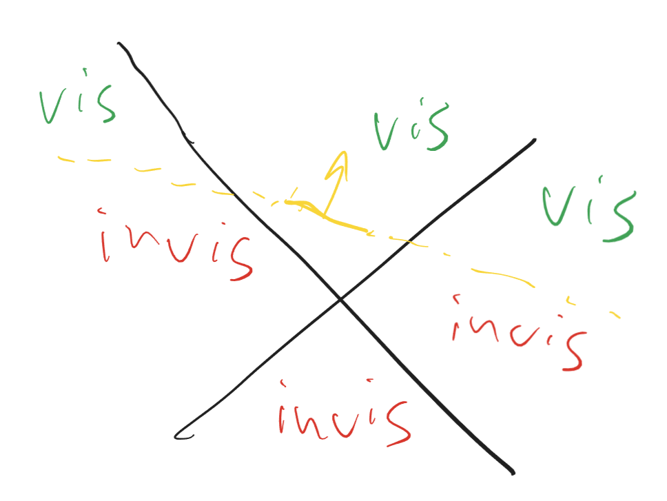
If the above does not hold for any of the rays, the region is not entirely in the negative half-space of the triangle plane and we must set the corresponding bit in the mask to 1. While this results in a conservative approximation of visibility, it’s not entirely precise - we’ll look at experimental results in a minute, but intuitively in a similar test done in 2D with the space split into four quadrants, most triangles would be classified as invisible only from one region out of 4, as the plane will intersect the other two and the fourth will be entirely in positive half-space:
This problem can be mitigated by increasing the number of regions - although that, in turn, will require more storage for visibility masks. For example, we can split each frustum region into four sub-regions, which requires a total of 24 bits = 3 bytes per triangle (the same amount of space as meshlet-local topology storage occupies). That also allows us to use a slightly simpler classifier:
int maskSide =
    max(abs(dir.x), max(abs(dir.y), abs(dir.z))) <= meshlets[mi].radius
        ? -1
        : (abs(dir.x) > abs(dir.y) && abs(dir.x) > abs(dir.z)
            ? 0
            : abs(dir.y) > abs(dir.z) ? 8 : 16)
        + (dir.x >= 0 ? 0 : 1) + (dir.y >= 0 ? 0 : 2) + (dir.z >= 0 ? 0 : 4);
Multiple cones per meshlet
In the technique above, we are limited to a fixed subdivision of space into regions, which can result in efficiency issues - we either use very few regions, which results in visibility approximation that is too conservative, or a lot of regions which can improve the culling efficiency but require a lot of storage.
An alternative variant of precomputed visibility is to use the same technique as cluster cone culling, but instead of only using one cone per cluster, allow multiple cones and specify which triangle belongs to each cone. For example, if we use 4 cones instead of 1, we could store the 2-bit cone id for each triangle, perform 4 cone tests in the task shader, send the 4-bit mask to the mesh shader and for each triangle, pick the correct bit to determine visibility.
To compute the cone id, we need to classify triangles into groups with similar triangle normals. For this we can use K-means clustering, which converges to a fairly optimal result in very few iterations. Once we have the cone id for each triangle, we can compute the bounding cone information for each subset of the triangles in the meshlet, and record the cone axis/angle. This can be done with repeated invocations of meshopt_computeMeshletBounds for each cone as long as the apex-less formulation of the cone test is used (see meshoptimizer.h for details).
Just as with cluster cone culling, we can do all classification in the task shader - however, unless all cone tests agree that the triangles are back-facing, we can’t reject the entire cluster, and need to pass the mask to the mesh shader invocation and perform the per-triangle test (here we’re using bitshifts to index into a mask using a 2-bit cone id):
gl_MeshPrimitivesEXT[i].gl_CullPrimitiveEXT =
    ((mconeCull >> ((meshletData[maskOffset + (i >> 4)] >> ((i & 15) * 2)) & 3)) & 1) != 0;
Estimating culling efficiency
For any given mesh, it’s fairly straightforward to analyze the culling efficiency offline: assume the camera is in a given position, run the classification/culling code sketched above, and count the total number of backface culled triangles. The results depend greatly on the mesh structure and the camera position; the table below summarizes culling rates for several meshes in a test set using each of the approximate culling techniques described above (keeping in mind that the optimal target is 50%)
| Algorithm | Kitten (niagara) | Happy Buddha | Sponza | Lumberyard Interior |
|---|---|---|---|---|
| Cluster cone culling | 25.2% | 28.0% | 7.7% | 4.2% |
| Precomputed masks (6 regions) | 10.4% | 10.6% | 8.0% | 10.2% |
| Precomputed masks (24 regions) | 26.6% | 28.2% | 24.8% | 24.6% |
| Multi-cone culling (2 cones) | 32.9% | 37.4% | 18.5% | 12.2% |
| Multi-cone culling (4 cones) | 38.1% | 42.5% | 28.5% | 24.3% |
As we can see, cone culling is very sensitive to the cluster composition - even when using 4 cones per cluster, we see very different culling rates depending on how the meshes are constructed. In contrast, precomputed masks give much more consistent results, although they also suffer from the dependency on triangle alignment vs region planes.
Unfortunately, neither 2 cones nor 6 precomputed masks get us close to the 50% target, and even with 24 regions the precomputed masks only get as far as ~25% culling efficiency. 24 masks require 24 bits per triangle; 4 cones require 2 bits per triangle plus ~16 bytes of cone data per meshlet (~3 bits per triangle total, assuming 128 triangle meshlets).
Additionally, cluster cone culling remains the only coarse test: for all other tests, reaching the indicated efficiency numbers requires per-triangle culling - for which we can always apply the brute-force option as well. While the tests require less ALU per triangle, they aren’t free - some amount of bitmask loading and bit extraction is still necessary, only to reach suboptimal efficiency. Ultimately, the only way to know if any of these techniques are worthwhile is to try them out in a real application.
Measuring hardware performance
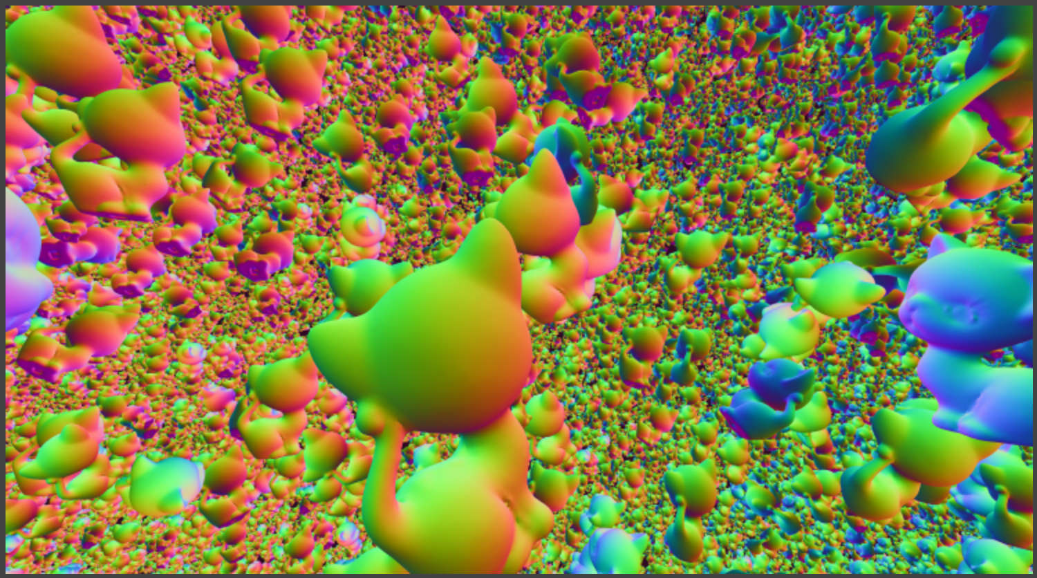
Lacking the patience to fully implement all of these techniques in a production renderer, I’ve implemented them in niagara. We are going to use the default kittens scene, and disable all other forms of per-cluster culling to isolate the performance impact of backface culling alone. While using the kittens mesh may seem to favor cluster cone culling due to the higher efficiency, this is partially mitigated by the use of level of detail - when level of detail is enabled, a lot of the scene is rendered using lower density meshes than the base mesh for which the results were reported above. We will see that it affects efficiency of cluster cone culling and brings it more in line with what we could expect for more realistic geometry.
The tests were performed on NVidia RTX 4070 Ti using NVidia NSight Graphics which measures the frame time while locking the GPU clocks, hopefully providing more stable results. For each method, we report the number of triangles rendered as well as the full frame rendering time - while that includes other passes, the workload is squarely dominated by geometry processing. The culling efficiency rate is computed as the percentage of triangles rejected compared to the baseline.
| Algorithm | Triangles (LOD) | Time (LOD) | Triangles (no LOD) | Time (no LOD) |
|---|---|---|---|---|
| Baseline (no culling) | 106.1M | 8.38ms | 729.8M | 55.20ms |
| Cluster cone culling | 91.8M (13%) | 7.25ms | 494.1M (32%) | 45.88ms |
| Precomputed masks (6 regions) | 92.4M (13%) | 8.58ms | 644.9M (12%) | 54.36ms |
| Precomputed masks (24 regions) | 74.4M (30%) | 7.61ms | 527.1M (27%) | 49.25ms |
| Multi-cone culling (2 cones) | 79.7M (25%) | 7.73ms | 445.6M (39%) | 45.79ms |
| Multi-cone culling (4 cones) | 69.3M (35%) | 7.13ms | 416.7M (43%) | 44.15ms |
| Brute-force culling | 49.4M (53%) | 7.63ms | 368.0M (50%) | 46.32ms |
| Cluster cone + brute-force culling | 49.4M (53%) | 6.96ms | 368.0M (50%) | 40.07ms |
As we expect, we see that the efficiency of mask-based methods is similar between LOD and no-LOD version, but the cone culling based methods lose efficiency in LOD version, as instead of a lot of very detailed meshes they have to work with a mix of coarse and detailed meshes. Also worth noting is that these numbers are measured on a configuration where each meshlet only has up to 64 triangles, and the earlier modeling table used 124 triangles as a maximum4.
What we may or may not expect is that while efficiency and performance do not correlate exactly, generally speaking spending more effort to cull more triangles pays off. This is especially pronounced in the brute-force culling version, which - while not the fastest - is a contender for the top 3 spot, despite simply doing, again, what the rasterizer is otherwise perfectly capable of doing. The notable exception to this is cluster cone culling, which saves a decent amount of performance despite the relatively low efficiency - but remember, cluster cone culling is the only method we’ve discussed that is able to perform culling on the cluster level, which makes the triangles this method culls much more valuable as they do not contribute at all to the cost of running the mesh shader.
As a result, combining cluster cone culling (to minimize the amount of work done by the mesh shader) with brute-force culling (to cull the triangles that cluster cone culling misses) gives us the best of both worlds: we get the performance of cluster cone culling with the efficiency of brute-force culling. This is the approach that niagara uses right now. All of the other culling methods are interesting, but fundamentally the bruteforce culling is cheap enough that the extra complexity doesn’t really pay off as none of the methods can reach the same culling efficiency. Of course, the results in a more production ready scene or on a different GPU may vary.
Note: I originally intended to rerun the experiments on AMD Radeon GPU, but these numbers take forever to gather, and based on my previous experiments with fine-grained culling on AMD hardware I suspect the results will hold even more strongly there, as seemingly any amount of ALU that is spent to cull triangles pays off there… Sorry!
Conclusion
In this post we’ve looked at a number of different techniques to cull backfacing triangles in mesh shaders. We’ve seen that cluster cone culling - which is the only method that can cull triangles on the cluster level - can result in suboptimal culling rates but is still valuable to reduce the mesh shader workload. When considering triangle-level culling methods, all of them seem to, in the end, lose to bruteforce culling or at best be on par with it.
The code for fine-grained culling, as well as cone culling integration, is available in niagara and meshoptimizer; mask-based culling is likely going to be added to meshoptimizer in the future as well even though it looks like it’s not going to be the best option for most use cases. Implementing K-means for cone cluster selection is left as an exercise to the reader ;)
-
There are other, more powerful, culling techniques that can make task-level culling of meshlets more effective, such as occlusion culling which is also implemented in niagara, but are outside of the scope for today’s post. ↩
-
meshoptimizer’s main algorithm for meshlet construction, meshopt_buildMeshlets, has a parameter
cone_weightthat helps control this tradeoff to a small extent, although the algorithm always prefers connectivity over orientation. All numbers in this post assumecone_weight = 0.5. ↩ -
Depending on the hardware implementation, you may or may not want to try also compacting visible triangles in the mesh shader. My experiments did not suggest that this is worthwhile on current NVidia or AMD GPUs, but that may change on other hardware. ↩
-
This discrepancy comes from the fact that niagara currently uses the only meshlet configuration that was reasonably performant on AMD hardware, and I didn’t invest the time yet to do rigorous cross-vendor tuning. ↩
| « Meshlet size tradeoffs | Efficient jagged arrays » |