Zigzag decoding with AVX-512
17 Jun 2026I’ve been working on speeding up AVX-512 vertex decoding in meshoptimizer recently; in the process I stumbled upon two optimizations that I did not end up using but I thought they might be fun to write about! The optimizations that actually made it in require some higher level background / explanations that will have to wait until another day :)
Both optimizations discussed here touch upon two new (for me) features of AVX-512 that I haven’t had a chance to experiment with until now, and both apply to the same problem: how to decode zigzag encoded integers.
Zigzag encoding
Suppose that you have a lot of signed integers to encode; and these integers come as a result of delta encoding, representing differences between input values. If the input values are reasonably close to each other, the resulting deltas are small in magnitude, but the sign of the deltas is fairly unpredictable.
We could encode the resulting deltas as is, in their two’s complement format - but that may be inconvenient if we want to encode the deltas using few bytes or bits. Ideally we’d like small deltas to be encoded with a number of bits that scales with their magnitude. A zigzag encoding gives us that property, and it transforms values such that positive values v are stored as 2*v, and negative values are stored as 2*(~v)+1. So 0 encodes as 0, -1 encodes as 1, 1 encodes as 2, etc. - positive values become even values and negative values become odd values. The sign bit is effectively shifted to the least significant bit.
To decode this, we can directly decode either a positive or a negative value1:
(v & 1) == 0 ? (v >> 1) : ~(v >> 1)
… or, use a common branchless decoding function:
(v >> 1) ^ -(v & 1)
The way branchless decoding works is that -(v & 1) is 0 when v is even, and a mask of all 1s when v is odd. Xor-ing with that mask keeps the magnitude (v >> 1) as is if the mask is 0, and inverts it if the mask is all 1s - which is equivalent to the ternary expression above.
The net effect is that the resulting value is a small positive value if the input was a small negative or positive value; we can then encode the result using any variable-width scheme of our choosing: common options include VByte (aka LEB128, which encodes unsigned integer values as 1-5 bytes) and other forms of bit-wise encoding2.
SIMD decoding
The branchless decoding function maps in a very straightforward way to any SIMD instruction set of your choosing: assuming you somehow already produced unsigned value v in each lane of a SIMD vector, you can easily write a (width-dependent) function that decodes the original signed value. For example, using SSE2, and assuming 32-bit integer inputs, we get:
__m128i xs = _mm_and_si128(v, _mm_set1_epi32(1));
__m128i xl = _mm_sub_epi32(_mm_setzero_si128(), xs);
__m128i xr = _mm_srli_epi32(v, 1);

return _mm_xor_si128(xl, xr);
This is a direct translation of the C code above, except that SSE2 doesn’t have an obvious first class way to negate integers, so you need to subtract from 0 instead. This compiles exactly as you would expect (and also supports any integer width and can use wider AVX2 or AVX-512 vectors in an obvious way)3:
vpsrld xmm1, xmm0, 1    ; shift by 1
vpandq xmm0, xmm0, xmm2 ; and with 1 (preloaded into xmm2)
vpsubd xmm0, xmm3, xmm0 ; sub from 0 (preloaded into xmm3)
vpxorq xmm0, xmm0, xmm1 ; xor
Every instruction used here has 1 cycle of latency on Zen 4; note that vpandq does not depend on the results of vpsrld, so the cumulative latency of the 4 instructions is 3 cycles.
Masks
The decoding transformation here is quite simple: our branchless formulation is expressed using arithmetic, but really it’s just moving bits around and occasionally flipping them. This feels like something that a sufficiently advanced bit permutation engine in hardware can do easily, and certainly dedicated circuitry here would be much simpler than an adder. But we make do with what we are given, and what we are given is AVX-512 - which mostly consists of unsurprising instructions (arithmetic, bitwise ops, etc.), and the obvious “surprising” instructions like vpternlogd (which allows creating custom bitwise functions that combine three bits into one using a truth table) do not seem to help here either.
There is, however, a different way we can go which is a little unusual if you’re used to earlier SIMD instruction sets: instead of using a branchless formulation and relying on various instructions that combine the results using bitwise ops, we can try to compile the branching variant directly.
Consider, again, our branch-based ternary expression:
(v & 1) == 0 ? (v >> 1) : ~(v >> 1)
To compute it, we need to produce the “magnitude” v >> 1, then check (v & 1) == 0 condition, and select between the magnitude or the inverted magnitude. In scalar code, this can be expressed as a branch; but because this computation is vectorized, we can’t emit a branch as the condition may vary per SIMD lane. What we can use instead, though, is AVX-512 predication support, or execution masks. In pseudo-code, this could look like this:
sign = v & 1
mask = sign != 0
res = v >> 1
(predicated by mask) res = ~res
Naively, this looks like the same 4 instructions: we compute the sign, compare it with 0, shift the original value by 1 to compute the result (for positive values), and invert the result conditionally only for lanes that computed sign as 1. AVX-512 does not have a bitwise NOT operation, but it has a XOR operation that can be conditional, so we can XOR with -1 instead. This can be directly expressed in AVX-512 like so:
__m128i xs = _mm_and_si128(v, _mm_set1_epi32(1));
__mmask8 m = _mm_cmp_epi32_mask(xs, _mm_setzero_si128(), _MM_CMPINT_NE);
__m128i x = _mm_srli_epi32(v, 1);
return _mm_mask_xor_epi32(x, m, x, _mm_set1_epi32(-1));
Again, by itself this does not seem useful; however, given a sufficiently smart compiler4, or a sufficiently deep knowledge of AVX-512 instructions, this can be optimized further. Specifically, we are doing an and operation and using the result to compute the mask; but, AVX-512 includes a dedicated instruction for this, similar to a scalar test instruction from x86, that performs and, compares the result to 0 and sets the mask when it’s not 0: exactly what we need! The code above, then, is equivalent to:
__mmask8 m = _mm_test_epi32_mask(v, _mm_set1_epi32(1));
__m128i x = _mm_srli_epi32(v, 1);
return _mm_mask_xor_epi32(x, m, x, _mm_set1_epi32(-1));
… and compiles to just three instructions (k1 here is a special AVX-512 mask register, equivalent to __mmaskN type):
vptestmd k1, xmm1, xmm3
vpsrld xmm0, xmm1, 1
vpxord xmm0{k1}, xmm0, xmm2
Neat! Instead of a register filled with 0, this requires a register filled with -1 in each component, but if this runs in a loop you can usually compute that once and use it for free.
One caveat is that this only works with 32-bit integers, because AVX-512 does not support masked 8 or 16-bit XOR! Fortunately, we need to conditionally invert the value, and instead of computing ~x we can compute -1 - x, which is a conditional subtract that AVX-512 does have for all integer widths:
__mmask8 m = _mm_test_epi16_mask(v, _mm_set1_epi16(1));
__m128i x = _mm_srli_epi16(v, 1);
return _mm_mask_sub_epi16(x, m, _mm_set1_epi16(-1), x);
Are masks faster?
We heroically reduced the instruction count by 1, but not all instructions are created equal. Is the result faster? The answer is, as all good answers are in cases like this, “it depends”.
First, if we look at Zen 4 instruction latency tables: we will note that while masked execution seems to be “free” (vpxor/vpsub with a mask has the same latency and throughput as the unmasked variants), vptestmd latency according to uops.info is 3 cycles; shift does not depend on the result, but the conditional xor/sub does, so our total latency here is 4 cycles - one cycle longer than the original version.5 So in cases where your code is latency-bound, this is probably a bad idea.
That said, it should be rare that the entire zigzag decoding is on a latency-critical path; even in typical code that takes the decoded value and accumulates it, the latency-critical path is the addition “spine”, and as long as you can read the inputs independently, an extra cycle of latency might not hurt.
In code that decodes many integers in parallel and is throughput bound, this might be faster. If we look at which ports these instructions get dispatched to on Zen 4, we will see something like this for XMM registers:
| RThroughput | FP0 | FP1 | FP2 | FP3 | |
|---|---|---|---|---|---|
| vptestm* | 2 | x | x | ||
| vpsrl* | 2 | x | x | ||
| vpxor* | 4 | x | x | x | x |
| vpand* | 4 | x | x | x | x |
| vpsub* | 4 | x | x | x | x |
Each instruction here can be dispatched once per cycle per port it can get executed on, but “simpler” instructions can execute on any of the 4 ports, and the two more complex instructions can execute on any of the 2 - critically, vptestm and vpsrl execute on two different sets of ports! Therefore if we do not have any latency constraints, it might be reasonable to expect that our old combination of vpsrld/vpand/vpsub/vpxor takes around 1 cycle for 4 instructions, whereas our new combination perfectly fills the gaps and might average ~0.75 cycles for 3 instructions. Of course, this is purely theoretical and also depends on whether we have any other instructions; if the code running alongside zigzag decoding really needs FP0/FP1 this might increase the port pressure and make it slower.
Experimentally, for meshoptimizer:
- In vertex codec, this is not very useful because the loop where this can be applied is bottlenecked by a combination of a latency “spine” that accumulates deltas and vector stores that overwhelm the store unit. The rest of the code has enough execution resources: even though the new code requires fewer of them, it does not change the performance.
- In meshlet codec, part of the decoding process is an actual throughput-bottlenecked loop (yay!); and in that loop, using this decoding method does indeed improve decoding performance measurably (~3%). However, meshlet codec currently does not have an AVX-512 (or even an AVX2) path; and making the decoding loop wider to match the AVX-512 register width might have a more significant impact.
In addition, this code works fine when compiled with GCC, but Clang decides it is a smart compiler and removes our mask trick entirely! Which ends up producing the exact same code we started from:
vpsrld  xmm1, xmm0, 1
vpandd  xmm0, xmm0, xmm3
vpsubd  xmm0, xmm2, xmm0
vpxor   xmm0, xmm1, xmm0
This behavior is simultaneously entirely unhelpful and also typical of Clang: LLVM loves to canonicalize vector intrinsics into forms that are ostensibly easier for the compiler to reason about, and then applies generic optimizations to these that are often either ignoring or misunderstanding the actual hardware bottlenecks. This is just fine for code that starts as scalar code and is auto-vectorized, but is actively harmful in this and many other cases when explicit SIMD intrinsics are used; there are sometimes ways to work around this, e.g. in the meshlet codec the actual expression we need is unzigzag32(v) + 1, which can be restructured a little bit to replace conditional xor with a more complicated conditional sub that LLVM leaves alone.
For all of these reasons this optimization didn’t quite make the cut, although I might revisit this at some point. But there is another interesting optimization we can consider!
GF(2) affine transformations
I’ve already mentioned it above briefly but it bears repeating: unzigzag is a very boring transformation of the underlying bits. If the low bit is 0, we simply shift the entire value right by 1. If the low bit is 1, then the resulting highest bit is 1, and all other bits are just inverted bits of the original value shifted by 1. There must be some circuit that just does it for us!
Enter GFNI, or “Galois Field New Instructions”. This is another extended instruction set; it’s technically not even part of AVX-512: it has a separate feature bit in the CPUID mask and must be checked separately; because of that, it’s also not part of AVX10.2 instruction set. However, all AVX10.2 CPUs support it, all AMD CPUs that support AVX-512 support it, and even though some earlier Intel CPUs (like Cascade Lake) support AVX-512 without supporting GFNI, at this point the existence of consumer Intel CPUs that have AVX-512 is questionable so we might as well assume the best.6 Definitely make sure to still check the CPUID bit, but my point is that relying on GFNI in addition to AVX-512 should not restrict our supported systems much in practice.
With that preamble out of the way, what do these instructions actually do? The most important instruction for our use case has a beautiful name vgf2p8affineqb and performs an 8x8 matrix multiplication in GF(2).
This will start making sense in a moment. Let’s take a byte, and represent it as an 8x1 vector x, with every vector component containing a single bit. And let’s take an 8x8 matrix, where each matrix element is also 0 or 1. We can then multiply the matrix A by the vector x using the usual arithmetic rules; then if we take the resulting integer vector and just take the least significant bit of the result, we will produce a new 8x1 vector, y (which can then be represented as a byte).
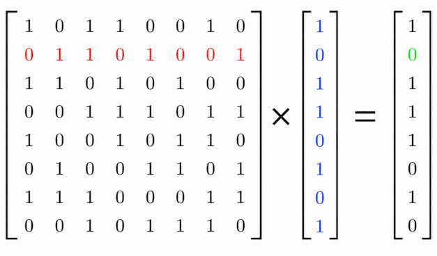
There are a couple different ways to think about this transformation. On one hand, this is just matrix multiplication, performed using modular arithmetic modulo 2 (by properties of modular arithmetic, it does not matter if you perform intermediate computations modulo 2 or just take the remainder of the final result). This is otherwise known as doing the matrix multiplication over GF(2), where GF(2) is a field that only defines two numbers (0 and 1), and defines arithmetic operations on them.
This means the matrix multiplication behaves much as other matrix multiplications do: you can combine two matrix transforms by computing a matrix product (also in GF(2)), and you can even invert some matrices which will allow you to represent an inverse of a given transform as a matrix too.
Another useful way to think about this transformation is by replacing * and + in the matrix formulation with and and xor: scalar multiplication over GF(2) behaves like and (both inputs have to be 1 for the result to be 1), and addition behaves like xor (adding 1 and 1 produces 0). Thus, the output bit in our bit vector is produced by taking the relevant row in the matrix, computing Aij and xj for every index j, and xor-ing the results together.
By controlling the matrix A we can control the transformation; transformations that are expressible in this way are called “linear” or “affine”, which is where the name of the instruction set comes from. Let’s see how we can apply it to our problem.
Deriving GF(2) matrix
While the GF(2) matrix transform can be defined over any bit width, the GFNI instruction set only gives us an 8x8 GF(2) matrix transform. This means we are limited to transforms that work on individual bytes. This by itself already restricts our set of applications quite a bit: while we never specified the zigzag transformation width exactly (it can work over any width), most uses of this transform tend to be over 32-bit values. However, in meshoptimizer vertex decoder one of the applications of the zigzag transform is exactly over the 8-bit values - perfect!
It currently uses a variant of the branchless transform described before; the one quirk is that SSE/AVX/AVX-512 do not support 8-bit shifts, so it needs to be emulated using a 16-bit shift with a mask, so the entire function looks like this:
__m128i xl = _mm_sub_epi8(_mm_setzero_si128(), _mm_and_si128(v, _mm_set1_epi8(1)));
__m128i xr = _mm_and_si128(_mm_srli_epi16(v, 1), _mm_set1_epi8(127));

return _mm_xor_si128(xl, xr);
This looks like 5 instructions, and it indeed is when compiled to earlier instruction sets, but AVX-512 lowering is a little more interesting:
vpand  xmm1,xmm2,xmm7
vpsubb xmm1,xmm8,xmm1
vpsrlw xmm2,xmm2,0x1
vpternlogq xmm2,xmm1,xmm9,0x6c
Shift, and, sub are matching the code we’ve looked at before, but the compiler replaced xor together with the extra and here with vpternlogq - which takes 3 arguments and a truth table defining how each of the 8 combinations of bits in the source arguments maps to the new result. This is nice because this makes the code as expensive as wider (16 or 32-bit) zigzag decoding even though it technically needs to work around the lack of 8-bit shifts7. Let’s see if we can do better.
As a reminder, the transform we need to represent is:
(v & 1) == 0 ? (v >> 1) : ~(v >> 1)
Let’s look at this transform in terms of how we would compute each resulting bit. If the source bit 0 (least significant) was 0, then the resulting bit K is equal to the original bit K+1 - the right shift by 1 moves it in place. If the source bit was 1, then the resulting bit K is the inverse of the original bit K+1. In other words, the resulting bit K is the xor between the original bit K+1 and the original bit 0 - exactly the structure we can represent with a GF(2) multiplication!
This is similarly clear if we look at the branchless decoding:
(v >> 1) ^ -(v & 1)
… and leads to a nice ability to compose the transforms8. Because ^ is, in GF(2), a variant of addition, if you’ve worked with matrices over regular numbers it should be intuitive that A*x + B*x = (A + B)*x. Therefore, a less direct way to construct our GF(2) matrix would be to construct a matrix equivalent to v >> 1, another matrix equivalent to -(v & 1) and xor them together.
In some cases you can go one step further and decompose something like -(v & 1) as a function composition (equivalent to matrix multiplication); unfortunately, in our case this doesn’t work because negation isn’t affine, and it only works here because v & 1 produces a 1-bit result; so it’s easier to think of this transformation as something that takes the low bit and propagates it to all bits of the output: if v & 1 is 1, the result is all 1s, otherwise it’s all 0s. This is a very simple GF(2) matrix, because every row of this matrix has 1 in the column corresponding to least significant bit, with all other values set to 0.
Which means we can finally specify both matrices and xor them together; the matrix that shifts bits right by 1 looks like this (e.g. first row copies the second least significant bit into the output):
00000010
00000100
00001000
00010000
00100000
01000000
10000000
00000000
and the matrix that broadcasts the low bit to all bits looks like this:
00000001
00000001
00000001
00000001
00000001
00000001
00000001
00000001
so the resulting matrix is an element-wise XOR of the matrices above and looks like this:
00000011
00000101
00001001
00010001
00100001
01000001
10000001
00000001
We are almost there: one final step is to pass this matrix to the instruction. The matrix is an 8x8 bit array, which is represented as a single uint649; the instruction technically supports multiple different matrices but in our case we need to transform all bytes uniformly, so we just need one constant uint64. To build the matrix, we simply take each row, convert it into a byte and concatenate the bytes together:
00000011 = 0x03
00000101 = 0x05
00001001 = 0x09
00010001 = 0x11
00100001 = 0x21
01000001 = 0x41
10000001 = 0x81
00000001 = 0x01
… and apply:
return _mm_gf2p8affine_epi64_epi8(v, _mm_set1_epi64x(0x0305091121418101LL), 0);
… yes, that is it, it’s just one instruction for the entire unzigzag8 transform, and it compiles to a single instruction (again assuming the matrix is already preloaded into the register).
vgf2p8affineqb xmm0, xmm2, xmm7, 0x0
Neat! Is it faster though?
Is gf2p8affineqb faster?
Well… The instruction itself is great - it has a 3-cycle latency on Zen 4 (so it should not be worse than our original code even in latency bound scenarios), and it can run on two out of four ports with a throughput of 2 per cycle; and our baseline AVX version requires 4 instructions (3 of which have a throughput of 4 per cycle), so in throughput-bound contexts this is more than twice as good. Unfortunately, due to the 8-bit limit on the value width there’s exactly one place in meshoptimizer where this would have fit (the vertex delta decoding), and there the results are inconclusive: this seems to help a little bit, but not very much, because as mentioned before the loop has two other more significant limiters:
- A latency-bound “spine” that accumulates deltas, which needs a cycle per addition;
- An army of short stores that also limit the throughput of the loop more than the computations do.
That said, similarly to the previous optimization, this is more of a property of the surrounding code and the actual optimization is quite sound; the downside being that it relies on yet-another not-quite-AVX512 instruction set extension, and it is limited to 8-bit integers - which are much less frequently used as a zigzag decoding width in the first place.
Still, that gave us a great excuse to try out a very powerful instruction! There are many other documented unconventional use cases for gf2p8affineqb that you can easily find online; in general if you ever are in need of a byte transform, double check if it is representable as a GF(2) matrix multiply - and rejoice if it is!
Note that
_mm_gf2p8affine_epi64_epi8takes an extra immediate which we’ve hardcoded as 0; this is thebpart ofAx+btransform, and while we haven’t needed it it may be helpful if you need to unconditionally xor any of the output bits with 1 after the matrix multiplication.
Conclusion
AVX-512 is quite fun to experiment with. I haven’t looked into this since 2019; it’s unfortunate that it still isn’t widely available, but it gives a lot of new interesting ways to approach existing problems, even disregarding the wider registers.
It’s a little sad that other instruction sets now have obvious gaps in relation to AVX-512; predication itself is not novel but many other instructions (GF(2) multiplication, compress/expand, multishift, bitshuffle) do not always have readily available equivalents in competing instruction sets like SVE2 (and while SVE2 is still evolving, the latest revisions of the ISA are nowhere to be found). A lot of the work I do requires designing formats that can be efficiently decoded on multiple instruction sets; so the degree to which all these new toys are applicable is a little limited as of yet. Hopefully this will change in coming years!
And I’m sure the AVX-512 story for meshoptimizer codecs is far from over too; there are still a few unexplored avenues and decisions that may not make sense on AVX-512 I should revisit. Maybe I will write another blog post after I do ;)
-
~(v >> 1)is equivalent to-(v >> 1) - 1; the extra offset is necessary as for negative numbers, we encode an offset magnitude into the higher bits. ↩ -
Here the assumption is that it’s important to maximize the number of leading zero bits to improve downstream compression; note that if you are targeting a general purpose LZ+entropy coder instead, simpler options exist too. ↩
-
This is using VEX encoded instructions, both to make AVX-512 comparisons more obvious, and to avoid discussing caveats around register renaming. ↩
-
Neither GCC nor Clang are sufficiently smart here; GCC does not recognize the pattern, and Clang does something terrible we will come back to in a moment. ↩
-
There is some confusion in the uops.info tables about what the latency of
vpxordis on Zen 4; I’m going to mostly ignore this as SURELY this must be a 1-cycle latency instruction. ↩ -
Yes, I know that Intel did used to ship laptop chips with AVX-512 enabled! I owned one in 2019 which is what the original AVX-512 support in meshoptimizer was tested on. But even that chip already had GFNI. ↩
-
Ironically, 8-bit shifts can be emulated with GFNI too, as we’ll see in a moment! But it would have been nice to get immediate 8-bit shifts still. ↩
-
This is arguably overkill here, as the full transform looks very simple on the bit level; however transform composition can be useful in more complex cases. ↩
-
Stored as a row-major bit sequence, and the byte order is a bit funky because the most significant byte stores the first row that determines the least significant output bit. ↩
| « Quantizing tangent frames |